This paper describes the design of a stepper motor controller based on 51 single chip microprocessor. At the same time, the subdivision driving technology is emphatically studied and the function expression of the reference current waveform of the subdivision driving is established.
In the design process, current tracking PWM subdivision drive technology is adopted.
A two-phase hybrid stepper motor driver is designed by subdivision model analysis and establishment. Based on the hardware schematic diagram of the driver, the working principle of each module is elaborated separately. Stepping motor is also called pulse motor or step motor. It is generally called step motor or stepping motor or pulse motor abroad. Its application and development has a history of about 80 years. Stepper motors have periodic errors but no cumulative errors. They have high accuracy. Stepper motors can achieve speed regulation, fast start-stop, positive and reverse control by changing pulse frequency in a wide frequency range.
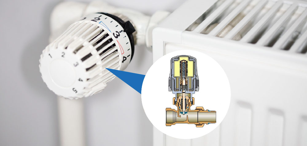
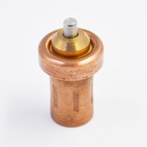
This is the most outstanding advantage of stepper motors. Stepping motors are also used in military instruments, communications and radar equipment, photographic systems, photoelectric combination devices, valve control, numerical control machine tools, electronic clocks, medical equipment and automatic plotters, digital control systems, industrial computer control, program control systems and many systems in the aerospace industry [2]. Therefore, the study of stepping motor control is particularly important. The typical structure of hybrid stepping motor is composed of stator and rotor. When the two-phase windings of the stator are electrified in the order of A-B-(-A)-(-B), the flux 1 passes through the permanent magnet, the first rotor core, air gap, stator core, air gap, the second rotor core, thermostatic element and the permanent magnet forms a closed loop to rotate the motor. This design uses subdivision mode of power supply, while two-phase hybrid stepping motor has four power supply modes: single-four beats, Double-four beats, single-eight beats and subdivision mode of power supply. The most important characteristic of the moment-frequency characteristic is that the torque produced by the motor decreases gradually with the increase of the motor speed, which determines that the stepping motor is not suitable for high-speed motion. This design chooses AT89C51.

When RESET has a high level of more than 2 machine cycles, reset is performed.
The reset circuit is shown in Fig. 4. A stable self-excited oscillator is constructed by a high gain inverted-phase amplifier in a single chip microprocessor chip, CRYS and fine-tuning capacitors Cl and C2. CRYS is 12M crystal, C1 and C2 are 30PF. DA/conversion circuit is mainly composed of two DAC0832 and two OP07 operational amplifiers. The connection mode and pin arrangement are shown in Fig. 5. RP52 is used to adjust the output voltage. RP53 is also used to adjust the zero of OP07.

Fig. 2, Tl494 adopts single-ended emitter output mode. The sawtooth wave generated by 5 and 6 feet controls the speed of PWM and compensates the zero and pole of current closed-loop feedback system.
The value of Tl494 is related to the internal parameters of the motor. Too much will cause the abnormal peak of current in the PWM operation too fast, and too little will lose the following degree of micro-step switching. The logic synthesis distribution circuit is composed of a GALI6V8 logic gate array and a ULN28O3 logic inversion power driver chip. The input signals of the logic integrated distribution circuit are two-way PWM signals SPWM-A, SPWM-B, A and B two-phase power transistors control signals AC, BC and turn on control direction signals DIR-A and DIR-B. These signals work to make the motor run.
The switch uses MOSEFT (IRF54O) as power device and the transistor IRF54O as H-bridge circuit. The power supply circuit uses three-terminal integrated modules LM7812C * 2, LM7815C and LM7805C chips to supply power for the system chip, and the DC voltage from transformer is supplied by the filter motor winding. When the precise resistance collects one or two values of the feedback phase voltage from the driving axle which exceed the comparative voltage, the low level output of LM393 passes through the gate circuit and generates the shutdown signal SD, which stops the motor from working. Research results and shortcomings: (1) Current tracking SPWM subdivision drive technology is realized, the equation of subdivision current reference waveform is deduced, and the driving principle of stepping motor is designed. (2) The 51 single-chip computer used has some limitations in operation speed and processing capacity. The accuracy of DAC is not high.