Standing on the design needs of liquefied natural gas (LNG) aerator, the corresponding system design can be completed. In this paper, according to the specific needs of the aerator control system, the author has worked out a practical scheme for many functions, such as I/V switching, keyboard operation, etc.
based on years of experience. Referring to the proposed scheme, the current related hardware circuits and software programs are designed scientifically. At the same time, corresponding hardware tests are made, and the design of the control system is well verified. With the fog and haze weather in different areas, people attach great importance to the protection of the environment, and the main cause of environmental pollution is that a large number of exhaust emissions from automobiles occupy the majority of the proportion. In order to better deal with this problem, people begin to look for new environmentally friendly fuels on the road of development. At this time, natural gas needs to be gradually penetrated into people’s eyes as a pollution-free and environmentally friendly fuel. The gas filler plays an important role in the gas filling station, and it is also an indispensable part of the measuring tools. Its control system is the core of the gas filler. Based on this, this paper mainly from the following aspects of analysis, put forward rationalization suggestions, to provide relevant people for reference. According to the design requirements, Fig. 1 is the overall design of the system. The liquefied natural gas (LNG) power aerator mainly includes mass flowmeter, pressure transmitter, temperature transmitter, solenoid valve, keyboard, power supply components, display part and control system.
According to the design requirements, we can set the density and single value by keyboard, click the pre-cooling key, open the pre-cooling valve, and the pre-cooling end signal is judged by PT100 signal control and flowmeter temperature. When the temperature is low – 1444 degrees Celsius, the pre-cooling valve is closed and completed when it is cold. Click on the add-liquid button, the add-liquid valve is connected, and the completion state of the add-liquid is collected by the flowmeter for 20 consecutive times. If the pressure acquisition signal is less than 0.01 or greater than 1.02 Mpa, the valve will be disconnected if the condition is satisfied. The display module can display the unit price, volume and total price information of small dosage during the filling process.
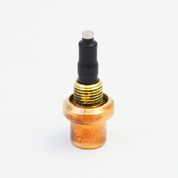
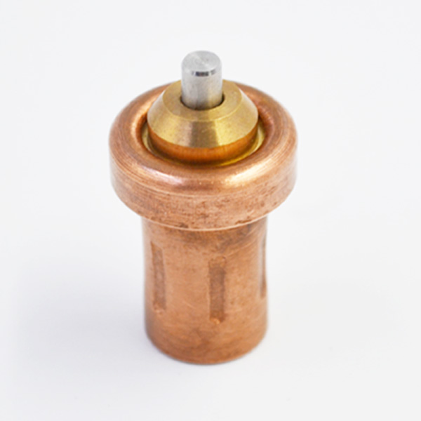
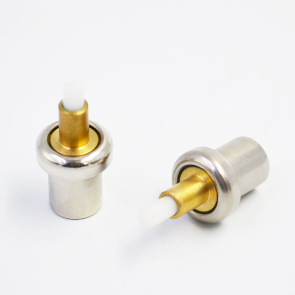
According to the design function of the above system, the hardware design of the system mainly includes the following parts: the front-end sensor data acquisition circuit based on single chip computer, MAX485 interface circuit, keyboard and display module interface circuit, output valve interface circuit, clock and storage circuit. The system mainly completes the front-end signal acquisition and judgment. When the setting conditions are satisfied, thermostatic element the pre-cooling and liquid-adding control is carried out by keyboard module, and the liquid-adding information is displayed and stored. The data transmission is carried out by serial port and computer. This paper focuses on the hardware circuit design of the control system.
The selected microcontroller is mainly produced by a company. The microcontroller is used to collect input signals of external sensors, interact with human and computer, and is responsible for data transmission with the host computer. In this paper, two independent keyboard modules and display modules are selected for the computer interaction part. When communicating with the control board, MC3487 and MCS486 are selected to solve the problems of level conversion and long-distance communication.

Keyboard is an important part of the peripheral circuit of the foot control system as an input device of human-computer interaction. The integrated keyboard module selected in this project has 16 keystrokes and a LCD bar. It can realize all kinds of input control operation only by connecting 6 wires with MCU. There are six lines in the keyboard module, which are the clock line, data line and serial data latch line pressed by HC165 empty keyboard, and the clock, data and latch line screwed by CD4094 chip in the keyboard display part. So we need two MC3486 chips, whose receiving circuit is shown in Figure 2. Because the main part of LCD is the output device of the gas engine system, and MC3487 chip has four related drivers, and any driver can be compatible with TTL for input buffer.
For the design of LNG aerator control system, in a sense and hardware design have played an indispensable role, and the performance of software will have a direct impact on the reliability of the aerator system. In this design, the modular design method is used by the relevant personnel, which brings benefits to the upgrade of the software system and its maintenance work. Usually, the functions of system software include many parts, such as serial communication, human-computer interaction and so on. There are two core parts in this design: one is the human-computer interaction part, the other is the data processing module part. Usually, the part used to present the information of liquid filling is a product specially designed by a company, which is presented by 3 *6 bits pen.

Usually, the driving voltage is 5V, and there are three interfaces which can be connected with the outside. They are divided into the following interfaces: the first is serial data input; the second is serial clock input; and the third is serial data latch signal. As far as the idea of display module programming is concerned, it can be understood that the unit price and the amount of liquid added should be designed scientifically in advance according to relevant procedures, and a practical algorithm can be worked out to calculate the total price displayed in the process of increasing the amount of liquid added. The function of keyboard is not only the main equipment for human-computer interaction, but also an indispensable link for the control of peripheral circuits. This topic mainly chooses an integrated keyboard module, and the keyboard module consists of two parts: one is a LCD display bar, the other is 16 keys. The keyboard only needs 6 wires to connect with the single chip computer, and then can operate different kinds of control properly. When adjusting the keyboard program, the relevant personnel are based on the design idea that when the number of LCD bars in the relevant system is zero, it will appear 1 after 2 seconds of stopping, then the relevant personnel can take the method of keystrokes to change the content presented, for example, according to K1.
After that, it shows 01, and then the related values show a significant increase. After the successful debugging of the keyboard module, the keyboard and the display unit can be grouped together, and the display can be controlled by the keyboard. The software of wave part of this part shows 0 after power-on, and the LCD part of keyboard shows 1 after 2 seconds of stop. At this time, the relevant personnel can design the unit price according to K2, K3 and K4 pairs. When the unit price is set, the unit price can be displayed in the relevant module.
Relevant personnel can start the gas filling system through K5 and K6. The display module starts from the position of 0 and stops after setting the gas filling volume.

The key K8 is used as the emergency stop key. When the relevant personnel press, the display module will not appear the charging situation. Through the discussion of the above content, we can know that: this paper mainly stands in the specific needs of LNG aerator, deeply discusses the relevant circuit and software program of the aerator control system in PLC, and studies the metering scheme formulated, so as to achieve the corresponding design. From the results of actual operation, we can see that it plays a preset role and realizes the design needs. However, after the prototype machine is designed in this design, there are still some shortcomings when it is used in practice.
After discussing the related hardware circuit design and its software program, it is a new attempt for the relevant personnel to use PIC MCU to control the gas filler, which can promote the strong promotion of the PLC MCU, and has important significance for promoting the development of LNG gas filler industry.
