With the gradual expansion of the solar energy market, more and more solar water heater controllers appear in the market, most of them are not perfect. At present, the control system of solar water heater in the market is basically digitized. The controller with single chip computer as the core occupies the main market of solar water heater controller, among which 51 series and PIC series single chip computers are the most widely used.
Solar water heater controller is the key part of the water heater system and the core of the whole system. This paper designs a general controller of solar water heater based on STC89C52 MCU. The whole idea is to measure and display the water level and temperature in the solar water heater container by the controller; automatically and manually water supply when water shortage occurs; and manually heating functions, which are verified by simulation and physical connection. Solar water heater uses sunlight to heat water from low temperature to high temperature, but in cloudy days, insufficient sunlight will lead to low water temperature. Therefore, it is necessary to cooperate with auxiliary heating device to elevate the temperature to the required temperature to meet people’s hot water use. At present, most of the control systems of solar water heaters in the market have the problems of single function, complex operation and inconvenient control. Although many controllers have the function of temperature and water level display, they do not have the function of temperature control or the error of control accuracy is large, and the reliability of the system is insufficient, which makes the use of water heaters inconvenient in cloudy days. Even if the water heater has the auxiliary heating function, it will overburn because the heating time can not be controlled, thus wasting electric energy. For this reason, a solar water heater controller with 51 single-chip computer as the core and low liquid level water addition and auxiliary heating function is provided, on the premise of guaranteeing perfect basic functions and considering economy. A solar water heating system is mainly composed of the following parts: collector, water storage tank, connecting pipeline, auxiliary heater, controller, etc. According to the structure characteristics of the hot water system, the solar hot water system can be divided into three types: forced circulation system, natural circulation system and direct current system. Solar water heater collector is the most critical device of solar water heating system. According to the structure of the collector and the different ways of heat absorption, there are three types of solar collectors on the market at present, including vacuum tube collector, flat plate collector and heat pipe vacuum tube collector.

There are many forms of auxiliary energy heating system for solar water heater. In practical design, comprehensive consideration should be given to user’s actual situation and convenient operation. At present, common auxiliary energy heating forms include built-in electric heaters, electric boilers, air source heat and so on. Users can choose appropriate auxiliary heat sources according to their needs, among which, electric heating is to use thermal resistance to heat cold water. Its characteristics are low cost and easy installation, but its operation cost is higher and its service life is short because the electric heater contacts with water directly, so its collection efficiency is high, its operation cost is low and it is green. Environmental protection, but its structure is complex, the initial investment cost is high. The controller of the solar water heater designed in this paper takes STC89C52 as the core and cooperates with other devices to realize the basic functions of the water heater. The hardware block diagram of the control system is shown in Figure 1. In this design, four resistance water level sensors are used. The internal structure of the sensor is simple.

Each probe in the water tank contacts a 25 K resistance in parallel. The resistance value in the access circuit changes regularly with the water level. The advantage of using resistance water level sensor to measure water level is to save cost, reduce circuit complexity and facilitate timely replacement. The disadvantage is that the resistance probe will produce a lot of scale when it is used in water for too long. In order to prevent this phenomenon, the resistance probe is packaged with stainless steel to prolong the service life of the water level sensor.
The temperature detection circuit adopts NTC thermistor temperature sensor with negative temperature coefficient, and the temperature measurement element adopts NTC thermistor. The resistance value of the thermistor with negative temperature coefficient changes with temperature increasing, resistance decreasing, temperature decreasing and resistance increasing. The display circuit includes water level display and temperature display. The water level display circuit is controlled by P2.4-P2.7 port of single chip computer.

The water level variables collected are processed by single chip computer, so that the output level of P2.4-P2.7 port controls the number of four light-emitting diodes on and off, so as to show the water level. Temperature display circuit uses digital tube to display temperature. Seven-segment LED digital tube is a display device composed of seven LEDs and one LED representing decimal point. It can display 10 digits such as 0-9 and decimal point. The circuit connection and use principle are relatively simple. Seven-segment LED digital tube is divided into common cathode and common anode. Common anode means that the anodes of LED are connected to common nodes. The cathodes of each LED are a, b, c, d, e, f, g and DP (decimal point). Common cathode means that the cathodes of LED are connected to common nodes.

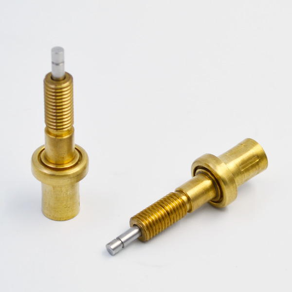
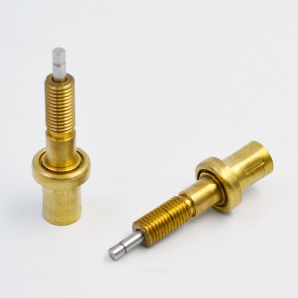
The anodes of each LED are a, thermostatic element b, c, d, e, f, g and DP respectively. The temperature of water heater should be able to display 0 to 99 degrees C. The design adopts the dynamic scanning mode of digital tube. The segment selection of digital tube is controlled by P0 port of single chip computer, and the position selection is controlled by P2.
0 and P2.1 port to realize the temperature display. Note that when P0 port is used as I/O port, pull resistance should be added. This design uses a common cathode digital tube, which defines the font codes of 0-9 as an array. By looking up the temperature data table, the corresponding numbers can be displayed. By pressing the button to send the water supply signal to the MCU, the high and low levels of the transistor are controlled by the output of the P3.0 port of the MCU, and then the on and off of the water supply relay are controlled. The P3.0 port connects the base of transistor Q1 through a 1K resistor, and 1K resistor is connected between base and emitter. The collector of Q1 connects the relay and reverse diode in parallel through water relay and 12V power supply. The Q1 emitter is grounded. When the output of P3.0 is low, the triode cuts off, i.e. collector current Ic_0 and base current Ib_0.

At this time, the current flowing through the relay is almost zero and the relay is turned on. When the output of P3.0 port is high level, the transistor Q1 is turned on, and the saturated current flows through the relay to make it suck and close, thus realizing the operation of water supply. By pressing the button to send the heating signal to the MCU, the heating electromagnetic relay is controlled by the port P3.1 of the MCU. When the output of the port P3.1 is low, the Q2 of the transistor is not conductive, the ground current flowing through the relay is almost zero, the switch is on, the electric heater is not connected to the circuit, and the relay is not heated; when the port P3.1 is high, the Q2 of the transistor is on, and the relay is saturated. The current flows through, the switch closes and the electric heater starts to work. By using resistance type 4-stage water level sensor, RC charging and discharging and time recording with single chip computer, water level signals are indirectly collected and processed by changing time recording to achieve the purpose of water level measurement. Using negative temperature coefficient NTC thermistor temperature sensor, RC charging and discharging, microcontroller recording different timing time method to achieve water temperature measurement. The above two modules are the most critical parts of the solar water heater control system. According to the brightness and extinction of four side-by-side light-emitting diodes, different water levels are displayed, and the temperature of water is displayed by digital tube.
This module is mainly used for human-computer information exchange, and can visually display the water condition in the storage tank of solar water heater. This module is the executive part of the system, including water supply circuit (triode, water supply relay), heating circuit (triode, heating relay) and so on. In the whole control system, microprocessor is the control core of the controller, which needs strong control ability, fast operation speed and rich peripheral resources. At the same time, in order to reduce the cost of the controller, microprocessors need to have a certain price advantage. This design uses STC89C52 single chip computer produced by STC company. The design of this system is based on STC89C52 solar water heater controller, which simulates in Proteus before connecting complex circuits to test whether the program design meets the relevant requirements of the circuit and whether the program runs correctly and reasonably. Proteus software is used to pull out the components needed in the circuit, draw the specific circuit diagram, and set the corresponding parameters of the components. Then the program written by Keil software is imported into MCU. According to the simulation circuit, the circuit is constructed by circuit board and minimal system board of single chip computer. After successful debugging, the complete circuit is constructed for comprehensive debugging. One of the keys to debugging is temperature calibration. To achieve temperature calibration according to specific circuit, linear calibration method is used to measure the resistance of thermistor at 0 C and 100 C.
According to the characteristic of exponential decline of thermistor, resistance at other temperatures can be calculated. Look-up table method is a linear interpolation method. It divides the non-linear function into segments, i.e. replacing each segment curve with a straight line. The more segments the error is, the smaller the error is. It draws the coordinate value of the break point into the graph. Using the linear equation of two points, it can get the value of other points between the two points, which can realize the temperature calibration. The physical connection diagram of water level display is shown in Figure 2.
On the circuit board, there are 555 timer generating square wave circuit, RC charging and discharging circuit, LM358 follower, LM393 comparator and four LED. On the upper side, there are 5V and 12V power supply, and on the right side, there are water level and temperature sensors. When the water level changes, the four light-emitting diodes brighten and turn off corresponding changes, can more accurately express the change of water level. When the water temperature changes, the digital tube can display the temperature more accurately, the error is less than 3 degree C. When the water supply button is pressed, the water supply relay acts to simulate the water supply. When the heating button is pressed, if the temperature is lower than 65 degrees C, the electric heating relay acts to simulate auxiliary heating; when the temperature rises to the set temperature, the electric heating relay loses power and stops heating. Basically meet the design expectations and requirements. This paper takes STC89C52 as the core, cooperates with four resistive water level sensors, NTC thermistor temperature sensor with negative temperature coefficient, digital tube and driving circuit (water supply relay, electric heating relay) to realize the expected function of the controller in the solar water heater container, and through simulation and physical connection. Verification is carried out.
