Vehicle-borne communication controller is the core device to realize the human-vehicle interconnection, which has a great impact on the electromagnetic environment of the vehicle. Based on the function and composition characteristics of the vehicle communication controller, the test scheme of its electromagnetic interference is studied, and according to its interference characteristics, the measures of restraining interference are put forward to meet the requirements of the vehicle. With the development of the automobile industry and the increasing demand for convenience of life, the products related to the networking of cars on modern smart cars are becoming more and more widespread and popular [1]. Taking the vehicle communication controller as an example, it realizes the data and information exchange between the user and the vehicle through the smart phone APP. It has the functions of remote control of vehicle engine start-up, remote control of windows, air conditioning, vehicle status inquiry, in-car call service telephone, anti-theft tracking and so on. It has many functions and high working power. Especially in the process of communication, it will produce large electromagnetic interference, which poses a new challenge to the vehicle’s electromagnetic compatibility performance. At the same time, as the integration of communication products and automobile parts, its electromagnetic compatibility performance test scheme is also different from the traditional automobile parts. At present, the application of vehicle networking products in China is still in its infancy, and there are few products with the same or similar functions on the market.
Therefore, there are few articles about the EMI test and its characteristics of vehicle communication controller in domestic journals.
Therefore, based on the function and composition characteristics of vehicle communication controller, this paper will study the test scheme of EMI characteristics of vehicle communication controller, and according to its EMI trunk. The disturbance characteristics and the measures to reduce the disturbance are put forward. The content of this paper is of great significance to the analysis and optimization of EMI of vehicle communication controller and the development of domestic vehicle networking industry. The object of this paper is a vehicle communication controller mounted on the CS75 high-speed distribution vehicle designed by Chang’an.
It is powered by the whole vehicle power network, and has built-in communication module and communication antenna. Based on the GSM [3] wireless communication mode, it provides corresponding GPRS data and GSM call service through the communication operator. At the same time, the controller has the function of sending and receiving CAN signals, communicating with the CAN network of the whole vehicle, realizing the conversion and interaction between CAN line data and GSM wireless data, thus realizing the corresponding function of controlling the electrical equipment of the whole vehicle and the communication in the vehicle. Its vehicle communication architecture is shown in Figure 1.
In order to satisfy the above functions, the block diagram of the internal equipment of the vehicle communication controller is shown in Fig. 2, and the main interference propagation paths are marked. From the above parts scheme and vehicle scheme, we can see that each control function of the vehicle communication controller is realized by GPRS wireless sending and receiving data, followed by GSM voice call. The problem of EMC (Electronic Magnetic Compatibility) is mainly focused on radiation disturbance, conduction disturbance to other parts of the automobile during the communication process of the controller, and disturbance to the data connectivity and call quality of the controller caused by the automobile parts and the external environment, resulting in the interruption of the connection [4]. The bench test of vehicle communication controller is different from the traditional EMC test method of automobile parts. According to the requirements of CISPR25, ISO11452 EMC and GB/T 22450[5] EMC of communication system of automobile grade, and according to the characteristics that EMC test can’t receive wireless GSM or GPRS signal in dark room, we adopt the following EMC test scheme of vehicle communication controller: using comprehensive tester to place outside dark room, keeping GSM with vehicle communication controller In the wireless communication state, 1 kHz voice call is played to the vehicle communication controller, and GPRS communication state is maintained with the vehicle communication controller, so that the vehicle communication controller is sent and received in a random signaling cycle, and the communication quality and connection monitoring are maintained.
The test plan layout and test photos are shown in Figures 3 and 4, respectively. Among them, the core instrument to realize the communication and data connection status of GSM and GPRS is a RS comprehensive tester CMU200, which is a measurement device to simulate the function of base station. Through this instrument, we can connect and communicate with GSM and GPRS for wireless terminal products, and set a series of communication parameters such as communication channel, transmission power, upstream and downstream time slots for wireless terminal products, and can be realized. The RXQUAL receiving quality and BLER block error rate of GSM and GPRS are measured. We put it outside the darkroom and connect it to the transmitting antenna in the darkroom through the signal.
At the same time, we connect the measurement and monitoring equipment such as CAN signal to achieve the purpose of complete and accurate measurement of the EMC performance of the vehicle communication controller. The performance requirements of setting and testing EMC test of vehicle communication controller with CMU200 are shown in Table 1, in which RE is radiation emission and CE is conduction emission. It is shown. From the above results and data, we can see that the vehicle communication controller will produce strong radiation disturbance in the process of GSM calls. From figs. 6 and 7, it can be seen that the average detection results of radiation emission test at the highest over-standard frequency point exceed the standard by 30 dB, and the average detection results at about 55 MHz exceed the prescribed limit. From Figure 8, it can be seen that the conduction and emission tests exceed the standard severely in the range of 1 MHz, 8 MHz to 25 MHz. This electromagnetic characteristic will have a serious impact on other parts of the vehicle and receiving equipment, but also bring difficulties and hidden dangers to the passing of vehicle regulation test. The results of observation and measurement show that the main points of over-standard radiation emission are 245 kHz to 30 MHz, starting from 245 kHz, and then the average over-standard radiation points are all harmonics of fundamental frequency. The over-standard radiation points of conduction and emission are 880 kHz, 6 MHz to 30 MHz, and their spectrum charts are a large number of narrow-band harmonics.
Combining the above spectrum results and the analysis of the internal structure of the vehicle communication controller, it can be seen that the over-standard situation of the communication controller is mainly caused by the unreasonable processing of various chips and clock switching signals in the controller. Among them, the typical operating frequency of audio power amplifier TPA2010D1 is 250 kHz, and the synchronous switch frequency of 12 V to 5 V DC buck chip TPS54240 is 1 MHz. To solve the problem of exceeding the standard in the test results, we should start with the direction of restraining the above sources of disturbance.
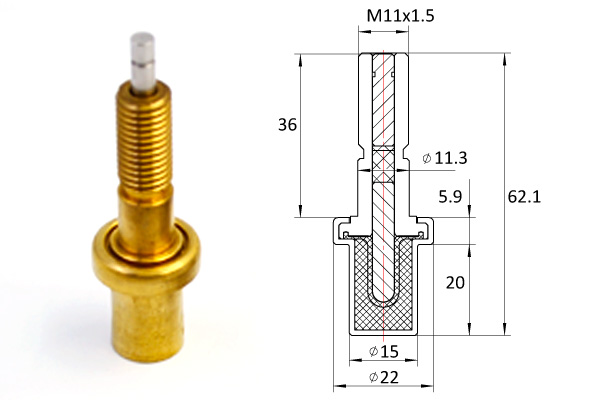
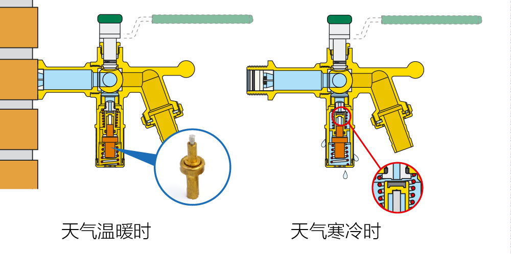
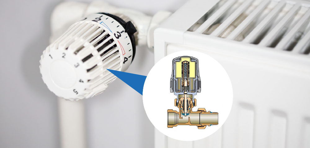
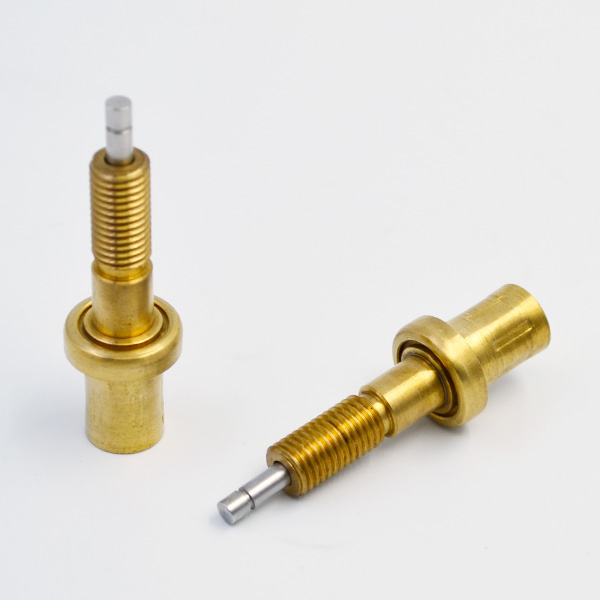
According to the over-standard frequency band of disturbance source and the impedance of filter capacitance, the harmonic and frequency-doubling interference produced by power chip should be added between BOOT and PH pins. The capacitance of 100 nF with good filtering effect of about 20 MHz should be added to the ground, so as to reduce the electromagnetic disturbance transmitted to the subsequent load circuit, reduce the crosstalk between lines and take it out of the communication controller [6]. For the audio power amplifier chip, the electromagnetic disturbance caused by the crosstalk between the internal and adjacent lines is mainly transmitted to the communication controller through the output of the loudspeaker. Therefore, common-mode differential-mode filtering is needed near the position of the power amplifier chip [7], thermostatic element as shown in figs. 9 and 10. The power input terminal of the communication controller is connected with the vehicle power supply. Generally, the electromagnetic interference in the controller will be transmitted to other vehicle electrical components through the power port. At the same time, the electromagnetic interference of other vehicle electrical components will also be transmitted to the communication controller through the power port, which will affect the normal operation of the communication controller. Therefore, the filter design of its power supply port is particularly important.
Fig. 11 is an optimization of the filter circuit design for the power input of the communication controller. According to the filtering frequency of capacitors and beads, 470 nF common-mode filter capacitors are used on the positive and negative poles, and porous beads are used to form a common-mode filter network to suppress the conduction common-mode current of 150 kHz to 30 MHz. At the same time, two 470 nF differential-mode capacitors are used between the positive and negative poles to form a pi-filter network [8] to filter out the low-frequency ripple to the controller and the external conduction. For the electromagnetic disturbance of radiation emission and conduction emission test, it is mainly transmitted through the external wiring harness of the communication controller I/O port. If I/O port is not filtered properly, a large number of electromagnetic disturbances generated by various chips will be brought out of the controller, resulting in radiation emission exceeding the standard. At the same time, external electromagnetic interference will easily enter the controller through I/O port, resulting in distortion of sound signals and screaming and misoperation of the controller. For the frequency range of 0.15 MHz to 30 MHz which disturbs the external conduction and radiation emission, the input and output processing of the I/O port signal of the communication controller is mainly through increasing the 100 nF capacitance to the ground [9]. As shown in Figure 12. From the following test results, it can be seen that after the implementation of the above optimization scheme, the excessive radiation emission and conduction emission have been tested to meet the corresponding limit line requirements. Compared with figs. 6 and 7, figs. 13 and 14 show a 30 dB reduction in low-frequency interference, a 15 dB reduction in high-frequency interference of 55 MHz, and a 6 dB margin. As shown in Fig. 15, the interference reduction is more obvious in the frequency range of conductive emission 1 MHz and 10 kHz to 30 MHz than in Fig. 8. After filtering and optimizing the main interference sources of power chips, power amplifier chips, power ports and I/O ports, the electromagnetic characteristics of the vehicle communication controller have been greatly improved, and the overall effect meets the expected requirements. Based on the function and composition of the vehicle communication controller, this paper studies the test scheme of the electromagnetic interference characteristics of the vehicle communication controller, and carries out the test work according to the corresponding plan, which can objectively and faithfully test the electromagnetic interference characteristics of the vehicle communication controller under the typical working conditions. From the test results, the EMI of the vehicle communication controller is strong and serious. According to its interference characteristic curve, starting with the overall framework, interference sources and interference ways, the measures to reduce interference are put forward.
After the actual implementation, the interference is effectively reduced, which meets the requirements of parts testing and vehicle use.
