Among all kinds of motor equipment, DC motor has been widely used in industry, metallurgy, machinery manufacturing and other modern industrial sectors for its good speed regulation, start-up and braking performance. In order to enhance the precise control function and portability of motor driver, the DC motor driver is implemented based on STM32 microcontroller. Research. Most DC motor drives are integrated in the system, relying on the drive instructions of the controller after analyzing and processing the external parameters to achieve various actions. Under the condition of integrated circuit, DC motor protection and drive can be completed, but the drive part can not be transplanted.
This research is to design a DC current based on STM32 microcontroller. Machine driver, which integrates motor control, detection, protection, communication and display, has the characteristics of fast response and high control precision, and also ensures portability. The main control chip of STM32 is used as the control system, and the other components are drive circuit, power circuit, detection circuit, display circuit, communication circuit, etc. The driver is designed as a dual motor drive mode, which can monitor, display and feedback the motor operation parameters in real time while completing the protection and driving operation according to the instructions, as shown in Figure 1. The driver uses STM32F103RCT6 microprocessor and is based on Cortex-M3 core. The highest clock frequency is 72MHZ. It has abundant peripheral resources, including DMA controller, ADC and advanced timer for motor control. It has powerful edge capture capability and PWM function, which can greatly simplify the design and reduce the total power consumption of the system. With SWD simulation interface, the pins are fewer, the connection is simpler and safer, and the code can be downloaded to Flash faster. The driver uses VNH3SP30 chip as motor driving unit. VNH3SP30 is a high current power integrated chip specially produced by Yifa Semiconductor Company for motor driving.
Its maximum current is 30A and power supply voltage is up to 40V. It contains under-voltage and over-voltage protection circuit. It has functions of overheating alarm output and automatic shutdown.
STM32 microcontroller achieves the control and signal feedback to the driver chip by optocoupler isolation.
SCM controls the high and low levels of INA and INB pins to realize the positive and reverse rotation and braking of the motor. PWM signals control the speed of the motor.

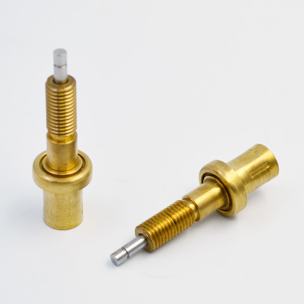
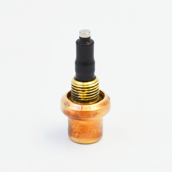
ENA and ENB pins realize the feedback of overheating, overvoltage, undervoltage and overcurrent of the chip, thermostatic element as shown in Figure 2. VNH3SP30 chip motor drive supply voltage 24V. In the power supply circuit, the input voltage of the power supply is 24V. The voltage is reduced to 12V, 5V and 3.3V respectively by LM2576S-12.0, LM2576S-5.0 and SPX1117IMPX-3.
3 voltage regulator chips. The detection circuit includes current detection, voltage detection and speed detection. It is mainly used to detect the current flowing through the motor, the voltage at both ends of the motor and the speed of the motor. The information of voltage, current and speed can not only provide protection for motor operation, but also be used to adjust the operating characteristic parameters of motor. Current detection component uses current sensor (ACS712), in which a high precision low bias linear Hall sensor circuit is installed, which can output and detect voltage proportional to AC and DC currents. Voltage detection is realized by voltage dividing circuit. DC motor is connected to resistance in parallel, and the output voltage of resistance is adjusted to the range of ADC acquisition of stm32. Speed detection reserves an incremental code disc interface, which fixes the code disc on the motor and connects the motor shaft with the code disc rotor. The processor calculates the speed of the motor by collecting the information of the code disc. The driver reserves LCD display circuit interface. LCD is connected to 16 ports of PA8-12 and PB6-7 of STM32 respectively. The speed, voltage, current and faults of motor driving are displayed. The communication circuit design uses SP3232 chip to realize the communication between the host computer and the motor driver.
It is used to realize the control of the steering and speed of the motor by the controller and the feedback of the operating voltage, current, speed and state of the motor. The software design is based on the firmware library of stm32. Compared with the direct control register, it can effectively reduce the programming difficulty and time-consuming.

The driver functions mainly include PWM control and ADC signal acquisition. Driver control is realized by pulse width modulation. By adjusting duty cycle, motor speed can be controlled. Considering the influence of voltage fluctuation and load variation on speed, PID algorithm is used to adjust speed fluctuation in this design.
Because ADC acquisition will be affected by voltage and current fluctuation, the data collected per second can be accumulated to 10 average values, and then the average values are compared with the critical values of motor undervoltage, overvoltage and overcurrent. If the critical value is exceeded, the fault state will be feedback; 232 communication mainly realizes the real-time control of steering speed and operation state of the motor by the upper computer. Based on STM32 microcontroller, this paper designs the drive and operation control of DC motor driver, realizes the monitoring and feedback of motor operation state in the drive part, saves the program space of the control system, improves the control accuracy, and gives the portability of the drive system.
