With the continuous development of science and technology and the intensification of market competition, China’s manufacturing industry has entered a more competitive environment.
At present, many enterprises in our country have low production efficiency and economic efficiency.
Compared with some developed countries, there are many problems, such as high consumption, high cost and low efficiency. This experiment is optimized by using program analysis techniques, operation analysis ideas and methods. The system uses battery as standby power supply, uninterrupted driving of experimental LED lamp and protection control of short circuit and break circuit of LED lamp. The safety indicator lamp is composed of 10 LEDs (rated power of single tube 1w). A driving converter is made to control the LED lamp group. The system has simple structure, and can keep the LED lamp on for a long time by using the backup battery to store energy.
This system is mainly composed of host module, display module, power circuit module design, battery module, DCDC buck module design, DCDC boost module design, small lamp circuit module design. The selection of these modules is demonstrated below. AT89C55WD is a low-power, high-performance microcontroller, 20K-byte flash programmable read-only memory and 256-byte memory. This device is a high-density non-volatile memory storage technology of artificial Atmel and 80C51 single chip computer and 80C52 instruction set in line with industry standards.
Through the analysis and demonstration of the subject, it is found that the whole system not only needs DCDC boost and buck, but also needs to display and control the liquid level. In this way, it not only needs to occupy a large number of I/0 resources, but also heavier the burden of CPU. Such a heavy task is difficult to achieve for ordinary MCU, and the performance is not stable enough. The control system of the controller of the LED uninterruptible power supply is designed. The test results show that the system is stable, reliable, easy to operate and powerful. The system analysis shows that the system needs to display the voltage and current between the devices and circuits. There are many items to display, and the digital tube display can not meet the requirements. Considering the cost, we finally decided to use two LCDl602 to display the data of two modules. This circuit mainly includes transformer step-down, bridge rectifier circuit, filter circuit, step-down circuit, AD conversion circuit, and digital display. The buck circuit is an efficient three-gain switching power supply DC/DC buck converter. When the circuit is in use, only the voltage regulator (adjustable resistance) of the power supply can be adjusted to obtain the required voltage between 15V. The power supply circuit realizes the conversion of 24V DC voltage to 15V DC voltage. Its working principle is: output DC voltage after step-down, rectification, filtering and voltage stabilization. When the converting capacitor array is set differently, a 15V continuous adjustable DC voltage can be obtained by changing the voltage dividing ratio.
DC/DC voltage module system is generally composed of three parts: main topology circuit, switch driver and feedback closed loop. The main topology circuit includes power switch, energy storage inductor, continuous current diode and filter capacitor, and the switch driver includes special chip for pulse width modulation and necessary circuit to enhance the ability of driving power switch. Through the analysis and consideration of the topic, the whole system can be divided into the following parts: power circuit module design, battery module design, DCDC buck module design, DCDC boost module design, small lamp circuit module design. The main advantage of using digital potentiometer is that it has high positioning accuracy, is not affected by mechanical vibration, and can realize semi-automatic regulation through program control.

The disadvantage of using digital potentiometer is that it can not be adjusted continuously. It is very convenient to use in discrete multi-gear regulation occasion. The adjustment accuracy of MCP41010 digital potentiometer reaches 256 gears, which is greatly improved compared with other 64 gears digital potentiometers. In addition, it uses SPI terminal, only needs 2B instruction reading and writing time sequence, and does not need to respond signal after writing 1B instruction, which brings great convenience to software simulation time sequence, which is its advantage.
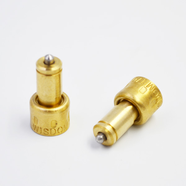
However, MCP41010 only integrates a potentiometer on a chip, using less resources, so it can use the same series of products MCP41010. According to the data, it can be seen that the LED UPS controller can basically complete the basic part, thermostatic element but the measurement accuracy needs to be further improved. The test results show that the system has excellent performance and is stable and reliable. This experiment provides energy for the small bulb through the battery again, which can make the small bulb continue to generate electricity, and DCDC boost and buck can completely protect the circuit and the bulb. The cost is low, and the use cost of the whole system is low. Compatibility is strong.
